Thursday, December 31, 2009

USB AVR Programmer

USB AVR Programmer
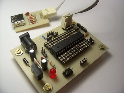
Serasidis says "Nowadays, USB is the most popular connection connection between PC and peripherals such as AVR programmers, printers, scanners etc. For that reason I had to modify my old serial AVR In-System-Programmer (ISP) to work with USB connection. You can say, "use a USB to Serial adaptor to connect your AVR ISP with your PC". Yes, that could be a solution but it would cost me more money than a singe FT232BM chip because I had to include an USB to RS232 adaptor and a power supply for my programmer. (almost €30)".

So, the solution was to replace the two transistors, that were used to adapt the RS-232 voltage levels to TTL voltage levels, with a USB to RS-232 chip such as FT-232BM.

This programmer worked perfect with AVRprog (zip file) but it could work with AvrOspII V5.47 also.

Download the source code, firmware, programming software, schematic and PCB for this programmer here
[source]

Wednesday, December 30, 2009

AVR Internet communications device

AVR Internet communications device
If you looking for Microcontroller project that controlled via internet protocol, well this project could be your reference to build it. Internet0 is a electronic project by Neil Gershenfield, Raffi Krikorian and Dany Cohen. The concept is a new network of physical objectsthat are IP enabled. Any items we use in everyday life would have the ability to communicate in IP, and thus send data over the internet in a standardized manner, without considerable electronics or cost.

This microcontroller project using AVR ATmega8 programmed ini C. For display they use LCD HD44780.

The main elements of the project are:

Transmission
to send a UDP internet0 protocol. Implementation:
o A circuit board with a Tiny15
o Assembly code to send the protocol
o Lines for power and signal
o An LED to troubleshooting and to indicate transmission

Reception
Translate the clicks to bits

PC Communication:
A program in Python that receives information from the serial port and transmit this into the internet

Read more

Tuesday, December 29, 2009

LM75 Temperature Sensor with 7 segment display output

LM75 Temperature Sensor with 7 segment display output
This is a test project built hastily on a solderless breadboard. It uses a LM75 to read the current temperature via I2C and displays the result on three 7 segment displays. It uses a PIC16F628 with an internal 4 Mhz clock. The program was created using JAL

[link source]

Sunday, December 27, 2009

MJoy- USB video game controller

MJoy- USB video game controller
This microcontrller project build using micrcontroller AT mega 8 and Xtal 12 MHz as the clock source.
"If you like to play video games in your computer as much as I do, you probably already heard about the MJoy, which is an USB joystick made by Mindaugas that uses an ATmega8 and have 24 buttons, one hatswitch (or POV or D-Pad depending on the game) and 6 analog axes." said Raijuu.

More information about this microcontroller project check the source here.

Saturday, December 26, 2009

Measuring Heart Rate on LCD using PIC

Measuring Heart Rate on LCD using PIC Did you know that The human heart can be measured optically. The heart beat with the varying blood pressure leads to a measurable change in the visual content of peripheral blood vessels. This is as good at the finger detect. There are two project work available, which were so far advanced that the optical signal pulse seized on a liquid crystal display graphically. Both works have been with a microcontroller PIC16C74 to collect and visualization of the signals.

Pulse measurement in a light
The light source was a red LED superhelle. The finger penetrating light was a light-frequency converter TSL230 detected. The period of the signal from the TSL230 was using the capture of the micro-controller unit with an accuracy of about 15-bit recorded. Through digital filtering 50Hz interfering signals were suppressed and the pulse signal extracted.

Pulse measurement in reflection
For the lighting of the skin's surface, an infrared LED used. the censor use PIN photodiode. With an analog circuit filters were equal light and high frequency interference signals eliminated. The signal was pulse by the A / D converter of the microcontroller with 8-bit digitized.

[Link]

Friday, December 25, 2009

LCD SWR Meter using PIC 16F88

LCD SWR Meter using PIC 16F88Measuring SWR at VHF/UHF frequency was never a fun. Most radio amateurs just assume that their 50 ohms cable is matching a beam or GP.

LCD SWR Meter presented here meet many simple task using a microcontroller PIC16F88. The very basic purpose to make this project is to encourage radio amateurs to build their own High Quality LCD SWR Meter at low price, instead of buying expensive ready made units.

[link]

Monday, December 14, 2009

Robot Project : Nickel-O-Matic

electronic robotic projectNickel-O-Matic was designed to entertain and provides gratuitous mechanical motion rather than efficient production. Nickel-O-Matic uses inkjet technology to print a custom message on both sides of 1-1/2" diameter blank wooden nickels. The robot uses a BASIC Stamp 2 to control much of the mechanical movement and a Propeller Chip to control the Inkjet system. The two controllers run a total of four hobby servos, three stepper motors, one DC motor, one DC vacuum pump, one inkjet head, and five IR sensors.


Mike Davey, the designer, said that the system was built as a number of modules to make design and trouble shooting simpler. The most complex of the modules is the inkjet system. At the center of the inkjet module is a spindle that rotates the wooden nickel under the inkjet head. This spindle is turned with a stepper motor and allows for repeatable placement of the nickel under the inkjet head. The spindle is also moved horizontally under the inkjet head by a second stepper motor coupled to a lead screw and slide mechanism. A Propeller Chip controls all the elements of the inkjet module. The Propeller Chip was chosen for the inkjet system for two reasons. The first is that the inkjet required fast and accurate timing. The Propeller Chip has direct control over the inkjet head through a simple Darlington transistor array. Each of the inkjet's 12 nozzles needs pulsed on for no more than 6 microseconds. The second reason the Propeller Chip was chosen is that the module needed at least 24 IO pins to control the inkjet module. The inkjet head needs 12 pins, the two steppers need 4 pins each, there are three IR sensors, and I needed at least one pin to communicate with the BASIC Stamp 2.

Download :


Source code

Sunday, December 13, 2009

PIC16F84 based Hexapod Robot

PIC16F84 based Hexapod RobotThis Hexapod Robot created by Mike Smyth. It uses 12 R/C servos for actuators. The 6 that raise and lower the legs are Hobbico CS-72 1/4 scale and the 6 that move the legs forward and backward are several brands of standard 1/10 scale servos (all are similar the Futaba S3003). The total robot weight is a little over 5lbs and the payload capacity is around 5lbs additional. The vertical travel of the legs is 1 7/8". Overall length and width is 13" X 11". When crouching, it's 5.5" tall. When standing up there is 3.5" of ground clearance under the body.


There are actually two PIC16F84's on the hexapod. The main processor contains all of the walking code and generates positioning pulses for all 12 servos. Twelve of the 13 I/O lines are used for switch inputs - one on the bottom of each foot and a contact sensor in the front of each leg. The servo pulses are output sequentially on the last I/O line. All the second processor does is de-multiplex the pulses from the main processor and send them to the appropriate servo

tag : Robotic, PIC16F84 Project, Electronic Design, Microcontroller Project (src)

Saturday, December 12, 2009

Minimechadon : PIC16F819 Based Walking Robotic

Electronic Project - PIC16F819 Based Walking RoboticMinimechadon is a great walking robot design by Mike Smyth. He creates Minimechadon to experiment with learning algorithms for walking. This walking robot weighs 12oz and has 4 degrees-of-freedom.

The sensor array consists of 4 touch sensors on the bottom of each foot, Left and right IR obstacle detection, and 4 CdS photo detectors located on all four sides of the robot. The heart of the control system is a Microchip PIC16F819 micro-controller and a separate 8 channel A-D converter.

The mechanical structure is built from brass tubing (which all the wiring runs through, UHMW (a high density plastic material), and PCBs. Perhaps the most striking aspect of the robot is the use of PCBs to create a 3D structure and mount all of the circuits/electronics.

tag : robotic design,PIC, Microcontroller, Electronic (src)

Friday, December 11, 2009

AVR Nikon Camera Remote Control

Nikon Camera Remote Control Microcontroller projectThis is an IR remote control for Nikon cameras. The circuit project is very simple: an ATtiny13V, button, transistor, resistor, IR diode and 3V battery. You can also connect the IR diode directly to the ATtiny13V, but that will limit the LED current and therefore the range. The project is compatible with the Nikon ML-L3 remote control. Supported cameras include: D40, D40X, D50, D60, D70, D70s, D80, and Coolpix 8400 8800. This project created by Dick Streefland

Thursday, December 10, 2009

Microcontroller Based Remote Sensing System

Microcontroller Based Remote Sensing SystemPageAlert is a flexible remote sensing platform connected to a data recording and alarm system. It is based on an MC13192 SARD board. This electronic project well designed by William Wittig. An MPXM2010 pressure sensor effectively senses the water level in a sump pump hole. The limited transmission range of ZigBee technology makes this wireless system ideal for home use.

Download
Project and Abstract

Wednesday, December 9, 2009

R/C Transmitter Range Tester

electronic circuit project - R/C Transmitter Range TesterThis project suitable for people who like with the transmitter system. It's an electronic analog project. You don't have to programming the IC to build it. The function of this electronic project is to measure the RF power being radiated from a transmitting antenna.

Among the Amateur Radio fraternity, a device such as the one described here would otherwise be known as a Field Strength Meter (FSM). Its main purpose would be to check that RF power is being radiated from a transmitting antenna. Some FSMs are tuneable across a wide range of frequencies, which allows the device to work with different transmitters and antennae - usually from HF to VHF and beyond. A difference with this unit is that it is only sensitive to those signals in the R/C section of the radio spectrum. The on-board trimmer allows you to tweak for maximum signal strength of your frequency of choice, whether it be 27MHz AM, or 40MHz FM.

In order to read the received signal strength, such a unit would ordinarily employ a mechanical analogue meter. The unit described here differs in that it uses four super-bright LEDs. The benefit of this is that it allows you to read the display from a distance - even in bright sunlight.

Download schematic(gif), PCB1, PCB2

Tuesday, December 8, 2009

PIC Project : Infra/radio remote control transmitter/receiver

PIC Project : Infra/radio remote control transmitter/receiverThis is a general purpose remote control project with programmable PIC microcontrollers. Schematics are shown for using infrared (RF) or radio (RF) media. If you are not familiar with microcontroller programming, you can use fixed encoder and decoder integrated circuits instead. Well-known such IC-s are Holtek HT-12D, HT-12E and Motorola MC145026, MC145027, MC145028.

Remote controls usually consist of encoder/decoder parts connected to a transmitter/receiver module which takes care of the transmission of digital signals by radio or infra waves. The format of this project's signal is designed to be ideal even for the cheapest ASK RF modules (using 50% signal/silence ratio), and it is similar to the Philips RC-5 format used in infrared remote controls. The transmitter has a varying number of buttons and sends the states of these inputs to the receiver. The receiver device decodes the message and sets the outputs accordingly.

Download schematic IR(jpeg), schematic RF
source

Monday, December 7, 2009

dsPIC MiniTron Amplifier

dsPIC MiniTron Tube AmplifierThe MiniTron is a high end vacuum tube stereo amplifier with efficiency, distortion, and power output enhancements provided by some unique circuitry featuring a dsPIC30F2023 controller IC. The dsPIC is used in this project to create a tracking buck converter whose output voltage tracks the audio signal. The unique SMPS resources in these IC’s do most of the "hard stuff" usually required in an SMPS design, leaving ample processing power available for other activities.

These IC’s and the Avago galvanic isolators are truly the "enabling technology" for this project. The controller IC is also used to perform system health checks, and set the operating points of the individual vacuum tubes. This allows total system programmability, offering several possible preset operating modes.

Download
Project Documentation

Sunday, December 6, 2009

dsPIC 33F128MC706 NUE-PSK Digital Modem

dsPIC NUE-PSK Digital Modem

PSK31 is one of the latest communications modes to capture the interest of hams worldwide. Its inherent ability to dig out low, near-inaudible signals is ideally suited for low power QRP enthusiasts. The PSK31 digital modem engine, however, requires intense DSP processing that is only commonly available in PC sound card. Thus the PSK operator desiring portability for field operation is locked into using a laptop computer as a controller, which results in a cumbersome station.

This project shows you design and construction of a standalone, battery-operated digital modem using a Microchip dsPIC microcontroller. The project includes a character display for transmit and receive text data, and a graphic display showing band spectrum and tuning indicator. Using GPL open source software, the modem can be homebrewed for less than $50 parts cost. When coupled with an SSB-capable transceiver or with a popular PSK-xx transceiver board from Small Wonder Labs, you too can have an effective portable PSK31 station.

Download
Project documentation

Saturday, December 5, 2009

AVR Digital Clock with Roman Numerals


This digital clock project will display a Roman number instead Hindu-Arabic numeral system (1,2,3... ). The project uses micro ATTINY2313 as main processor and LCD to display the clock. When you turn on the device, it will shows a screen flashes "Tempera tempus" as reminder to adjust the time.

The adjustment is done via the small button.
  • Press and hold the button for about 3 seconds -> hours appear on the screen -> release the button.
  • Press the button again and hold -> the hours advance from "I" to "XXIV" -> release the button on the time right.
  • Wait about 3 seconds -> minutes to appear on the screen.
  • Press the button and hold -> the minutes advance from "nothing" to "LIX" -> release on just minutes.
Unfortunately, you have to readjust the time after your turn off the power, because there is no RTC in this project.

Download schematic and source code here

Friday, December 4, 2009

Simple PIC RF/Microwave Frequency Counter

PIC RF/Microwave Frequency Counter

This RF/Microwave Frequency Counter project built based on PIC 16F876A. The basic counter rate is extended to at least 180MHz using two 74Fxx devices. A divide-by-64 prescaler is used for higher frequencies up to at least 4.5GHz. All results of the measurement are shown on an inexpensive, 2x16 alphanumeric LCD module with large characters.

There are 3 inpust on this project a microwave (prescaled) input, an RF input and a TTL input. The microwave and RF inputs are AC coupled and terminated to a low impedance (around 50ohms). The TTL input is DC coupled and has a high input impedance. A progress-bar indicator is provided on the LCD for the gate timing.

Both the microwave and RF inputs have an additional feature : a simple signal-level detector driving yet another bar indicator on the LCD module. This is very useful to check for the correct input-signal level as well as an indicator for circuit tuning or absorption-wave-meter dip display (Lecher wires). This project designed by Matjaz Vidmar.

tag : RF counter, Microwave Frequency counter, PIC project source

Thursday, December 3, 2009

AVR Shark Tag Project

microcontroller project animal tag

The goal of this project was to develop a shark tag working bench-top microcontroller platform. It is to be used for on-animal, in-situ data logging applications involving sharks and potentially other large pelagic.

The project used the Atmel Mega32 microcontroller to develop the core platform and functionality of a data archival tag. The project use temperature and pressure as sensor variable. The tasks ranged from logging sensor data to developing a simple user interface that requires only the addition of a laptop and a custom RS232 serial cable in the field.

It used an off-the-shelf SD (Secure Digital) card using flash memory for large capacity multi-read/write data storage. The microcontroller’s ADCs (analog to digital converters) were used to convert analog voltages produced by select sensors into digital format.

Tag: Animal Tag, shark, data logging, avr project src

Wednesday, December 2, 2009

XBOX Controller Controller

XBOX Controller Controller

What is this? It's a system that will allow basically anything that can talk udp to control an Xbox. Why would you want to do this? I have no idea. I have my reasons, maybe you have some too. How this works: The XBOX buttons are physically pressed by arms (stiff wire) attached to servos that are controlled by a Basic Stamp 2. The BS2 is controlled by a gumstix over a serial port. The gumstix talks udp and accepts commands. So if you want to control an xbox, you basically have to talk a simple udp protocol to the gumstix.

xbc-c-controller

For this I tried 2 controllers, a PSP and a Nintendo DS. The udp protocol is simple. Build a message with the status of your controller, and the system takes care of moving the physical fingers on the xbox controller. The protocol is as follows: '!!' for start of message, and '##' for end of message. The juice of the message is a 1 character button identifier, followed by a 1 byte state. 1 means the button is pressed and 0 means button is not pressed. Here is a sample message:

!!U0D0L0R1A1B0X0Y0##

The message should be self explanatory. So the controller (in this case the psp or nds) polls inputs every so often and then dumps the state. I had it all working at every 100ms, but then something happened - not sure what - so I backed it down to every 250ms. The bottle neck is on the BS2, and to keep things consistant, I just kept all polling intervals the same.

The app on the gumstix consists of 2 threads. One listens for udp commands and the other babbles out the serial port at 38.4k. The serial thread wakes up every 250 ms and sends the status of all buttons to the BS2. The status is stored in global variables that are updated by the udp thread whenever the controller sends an update.

The serial protocol to the BS2 is simple. A 'A' signifies a start of message followed by 8 bytes of status for each of the buttons currently supported. The PIC decodes this message and tells the servos to respond accordingly.
xbc-c-pic

PIC Cactus LED Display

LED Cactus Display PIC Project

LEDactus is LED display project that resemble Cactus. It used PIC microcontroller 18F1320 as controller of the LED. LEDactus is immobile and attempts to survive by creating a pleasant display. It can produce more complex and mesmerizing displays. And in the latest generations, a sense of touch is added to allow the LEDactus to interact with passersby.

term : LED display, electronic cactus, PIC project (src)

Tuesday, December 1, 2009

USB PIC Programmer

If you start learning PIC microcontroller, you need PIC progrmmer to "fill" your PIC with compiled source code. You can build your own PIC programmer like USBPICprog project.

Usbpicprog is an USB in circuit programmer for Microchip PIC processors. The hardware is as simple. The latest version only contains one PIC18F2550, 3 mosfets, and besides the connectors a hand full of passive components.

download
Open source programmer

Monday, November 30, 2009

Arduino Digital Thermometer

Arduino Project Digital Thermometer
This Digital Thermometer based on famous Arduino board and LM35DZ as temperature sensor. The sensor component has three pins, +5V, ground and a variable voltage output to indicate the temperature. This simple project wired the sensor output straight to the Arduino's analogue input 0. As display, it use two line LCD (a Displaytech 162B).

Tags : Temperature Measurement, Digital Thermometer, Arduino project src

Sunday, November 29, 2009

PIC LCD Oscilloscope for Spectrum Analyzers

PIC LCD Oscilloscope for Spectrum Analyzers
This is simple and inexpensive LCD oscilloscope for spectrum analyzer display. The project use PIC 16F876A as main processor. Although a small LCD screen is not as good as analog oscilloscope, a LCD oscilloscope may be very useful in field measurements, for battery operation or you need different measurement at the same time along with oscilloscope.

The 80dB scale of this LCD oscilloscope can be adjusted with the two trimmers providing the reference voltages to the A/D converter. The operation of the LCD oscilloscope is slightly different between the 80dB mode and the 40dB mode. In the 80dB mode, the trace is always visible and saturates on the bottom or top of screen. In the 40dB mode, the trace runs out of the screen and only the central part of the original 80dB scale is displayed. This project designed by Matjaz Vidmar.

Download
Source code, documentation and schematic

Saturday, November 28, 2009

AVR Project Wii Conductor

AVR Project Wii Conductor
This AVR project is a simplified implementation of Wii-Music, utilizing a Nintendo Wii Remote (“Wiimote”) to play a gesture-based music game with the player as a virtual music conductor. The project exploited two of the Wiimote’s features: its wand-like shape and the embedded 3-D accelerometers. By interfacing between Microcontroller AVR ATmega 644 and Wiimote, the project able wirelessly transmit motion gestures and button pushes to the MCU. The MCU uses these inputs to create sound by means of Direct Digital Synthesis (DDS).

Tags: Wii Conductor, Simplified Wii Music, Microcontroller AVR project src

Friday, November 27, 2009

PICTalker - Low Cost PIC Speech Synthesizer

PICTalker
PICTalker is a low cost allophone-based system for synthesis speech. The system use PIC16F628 microcontroller as main processor. You need a PIC development system and programmer, and Microsoft QBasic to program the microcontroller and EEPROMs to build this poject.

Speech quality is somewhat inferior to that from an SPO256 system. Most people immediately understand most or all of the speech it produces provided sufficient care is taken when constructing words from the component allophones. The speech is significantly easier to understand if the loudspeaker used has poor base response.

Download
Documentation and source code

Thursday, November 26, 2009

Simple AVR USB Temperature Probe

This simple USB temperature probe uses the AVR USB library by Objective Development. The included ruby script reads the temperature and optionally logs it using RRDTool. The EasyLogger would send the data values over a keyboard interface. The project uses a custom device class and reads values using the ruby-usb library. The project primarily intended to be used in Linux, although it is possible to get it to work in XP with a bit of hassle involved.
Download
USB Temperature Probe Documentation

Wednesday, November 25, 2009

I2C Bus Analyzer with USB link to PC

I2C Bus Analyzer
I2C-bus analyzer is a electronic project that has function to capture all transmissions via I2C/TWI bus, decode it and send to PC via virtual RS-232 port. Received data can be displayed by any terminal program on PC computer. The project use ATTiny2313 microcontroller with 20MHz crystal as main part. Link to PC are realized by FTDI FT245RL on UM245R module.

Download


Tuesday, November 24, 2009

Digital Clock using Classic LED 7 Segment Displays

Simple digital clock PIC project
This is a simple digital clock project using PIC16F887 and classic LED 7-Segment from HP 5082-7414 created by punkky. The displays are bright red and sun light viewable. Each clock consumes about 0.25W (50mA, 5V) when the PIC16F887 operates at 250kHz (display refresh rate is about 61Hz).

Tag: digital clock, 7 segment display, PIC project src

Monday, November 23, 2009

PIC Debugging Tool

PIC in circuit debugger tool
In-Circuit-Debugger is handy and easy PIC debugging tool for PIC programmers that interface to the target PIC placed- board. The device comes with MPLAB plug-ins that provides a full rich set of commands and functions in order to debug your code in real time. The project created by Electrical Engineer Atanasios Melimopoulos.

Download
In-Circuit-debugger

tag : PIC debugger, PIC programmer tools, PIC project src

Sunday, November 22, 2009

Parallel Interface AVR Programmer

Parallel Interface AVR Programmer Project
With this project you can program an AVR microcontroler ATMEL (ATmega8, ATMega32, ...) from a parallel printer LPT1 using ISP functionality In System Programming. This programming type can program and/or configure microcontroler directly on the target board without removing device and put it on a separate programmer. This board is compatible with programming software "PonyProg".

Download :
Schematic and Source Code

tag : AVR programmer, Microcontroller Project, Parallel Interface

AVR Based Diode Temperature Meter

Temperature MeterThis is Multi channel diode temperature meter project with Microcontroller AVR AT90S2333 as main controller. It can be use to replace thermister temperature meter.

Front end of the temperature sensor and amplifier circuit consists of constant current. Approximately a constant current of 63µA sensor (diode) in the sink, a diode voltage drop of 3-fold amplification and A / D converter (10bit, 3.3V/fs) type. Drift in this block is the main cause of measurement error, the components must be selected as the low temperature drift.

Where an adjustment is not analog, EEPROM calibration parameters are calculated from the temperature to make sure that you store in it. The calibration process is required for proper equipment such as computer terminals instead of the driver. Some cases, ISP via cable (N81, 38.4kbps) has been to enter the calibration mode is turned on and connected.

Download:
Schematic and source code

Tag: Temperature Meter, Microcontroller AVR project, electronic project (src)

Tuesday, November 17, 2009

ARM USB Data Acquisition

ARM Project USB Data AcquisitionThis project shows you how to build a simple data acquisition device around an LPC2138, ARM-based microcontroller. The system features a simple GUI that allows you to view graphed data instead of the streaming serial data in a terminal emulator session. In this project, Bruce gives example by collects temperature data from an analog temperature sensor and graphs it via a PC GUI.

Download
Source and PDF

Wednesday, November 11, 2009

Pin Diagram

OSC1/CLKIN: Oscillator crystal input.
External clock source input.
OSC2/CLKOUT: Oscillator crystal output.
Connects to crystal or resonator in crystal oscillator mode.
MCLR(inv): Master clear(reset)input.
Programming voltage input.
This pin is an active low reset to the device.
RA0 - RA3:Bi-directional I/O port.
RA4/T0CKI: Bi-directional I/O port.
Clock input to the TMR0 timer/counter.
RB0/INT: Bi-directional I/O port.
External interrupt pin.
RB1 - RB7:Bi-directional I/O port.
VSS:Ground
VDD:Positive supply(+2.0V to +5.5V)

The PIC is the small computer


The PIC, like the CPU, has calculation functions and memory, and is controlled by the software.
However, the throughput and the memory capacity are low. Depending on the kind of PIC, the maximum clock operating frequency is about 20 MHz and the memory capacity (to write the program) is about 1K to 4K words.
The clock frequency determines the speed at which a program is read and an instruction is executed. The throughput cannot be judged with the clock frequency alone. It changes with the processor architecture. However within the same architecture, the one with the highest clock frequency has the highest throughput.
I use a 14-bit WORD for program memory capacity. An instruction is a word long. Program memory is measured in BYTES, one byte is 8 bits. The bit is the smallest unit, and can have the value of 1 or 0. The instruction word of the PIC16F84A is composed of 14 bits. 1K words is equal to 1 x 1,024 x 14 = 14,336 bits. To convert this to bytes divide it by 8 x 1024, (14,336 / 8 x 1024 = 1.75K bytes).

A memory capacity of 1G bytes = 1,024M bytes, 1M bytes = 1,024K bytes, 1K bytes = 1,024 bytes. 1K bytes is not equal to 1000 bytes. This is because the calculation is in binary (2 to the tenth power = 1,024).

Tuesday, November 10, 2009

Basic Control


Microchip provide flexible products and solutions to take care of the basic control needs: Data storage ( Flash, EEPROM), Math functions ( up to DSP capabilities), timers, communication channels ( USART, LIN, I2C, SPI, USB, Ethernet, RF).

Our products and solutions are tailored to support multiple types of appliances:

    White Goods and Kitchen Appliances like Refrigerators, Ovens and Laundry
    Residential Thermostats, and HVAC

    Portable Kitchen Appliances like mixers and blenders

Only Microchip provides everything a design engineer needs:

    Low Risk product development
    Lower total system cost
    Faster time to market
    Outstanding technical support
    Dependable delivery and quality

Ethernet

INTRODUCTION

Welcome to the Microchip Ethernet Application Design Center.

Ethernet solutions are gaining popularity in the embedded connectivity space. There are several key reasons that drive such adoption. Ethernet is ubiquitous and it is the most widely deployed network in many offices and industrial buildings. It is based on IEEE802.3 that ensures reliability of network connections and data transmission. Moreover, the networks are scalable from the simplest to most complex networks. Finally, once equipment is connected to the network, it can be monitored or controlled through the internet.

Microchip addresses the growing demand for a small and low-cost embedded Ethernet solution by offering the following:

10/100 Base-T ENC624J600 standalone Ethernet controllers which are IEEE 802.3 compliant, integrated with hardware cryptographic security engines and factory preprogrammed unique MAC address. This family is fully compatible with 10/100/1000 Base-T networks

10 Base-T ENC28J60 standalone Ethernet controller and the PIC18F97J60 family, which are IEEE 802.3 compliant and fully compatible with 10/100/1000 Base-T networks

Free licensed and robust TCP/IP stack, which is optimized for the PIC18, PIC24 and PIC32 microcontroller and dsPIC digital signal controller families

EUI-48™ and EUI-64™ enabled MAC address chips along with Serial EEPROM functionality

A broad range of development tools to enhance the user’s experience

With Microchip’s scalable development environment and free TCP/IP stack, you can quickly integrate Ethernet functions into your existing application, thus reducing development risk, total system cost and time to market.

Monday, November 9, 2009

Automotive Design Center


Innovative Electronic Solutions Driving Faster Time to Market
Microchip Technology provides more than just embedded control silicon solutions that feature the industrys best price/performance value. We provide a low-risk product development environment, lower total system cost and faster time to market. Our innovative solutions for the ever-expanding spectrum of electronic control units in the vehicle give our customers a competitive advantage. Our commitment to quality and innovation coupled with world-class development tools, dependable delivery and outstanding technical support set us apart. Put Microchip in control of your next embedded design.

Add voice or audio features to your application

Voice continues to be a popular and natural medium of communication and human interface. Interfacing embedded applications using voice in local languages can help cater products to regional needs. Audio can also help interfacing electronics to the visually impaired. Microchip analog, memory, MCU & DSC products, software and tools enable simple applications to system-on-chip implementations.

Sunday, November 8, 2009

The PIC was developed as a peripheral controller


PIC(Peripheral Interface Controller) is the IC which was developed to control peripheral devices, alleviating the load from the main CPU.
Compared to a human being, the brain is the main CPU and the PIC is equivalent to the autonomic nervous system.

GPIB to USB converter Using PIC

GPIB to USB converter Using PIC

PIC-plot now goes to USB! A perfect low cost solution to quickly get screen plots of your GPIB instrument on your laptop PC without complex software. It emulates the HP7470A operation on the GPIB side, and outputs the HP-GL data at the USB port to be read and stored on the PC by any capturing software. GPIB addresses and other set-and-forget parameters can be configured by a simple Setup menu, then no Dip-switches are used. Power is taken from the USB port to simplify cabling and get rid of a DC adaptor.

The operation of this interface is not just limited to digital plotter emulation: any data intended to be received by a GPIB Device (addressable or listener only) can be captured from the instrument and brought out to the USB port, including raw measurement arrays or rasterized data for a graphic printer. It is based on a PIC16F628 microcontroller and an FT232R chip. PCB size is just 57x64mm.

USB Audio Digital to Analog Converter

USB Audio Digital to Analog Converter

I want to build high quality preamplifier with built-in DAC from SPDIF or USB for my power amplifier Leachamp. I tried to design DAC from USB with this circuit on one-sided PCB and I was successful.

Schematics is from datasheet of PCM2902. Circuit includes DAC and ADC, SPDIF output and input and HID part with 3 buttons for MUTE, VOL+ and VOL-. I used only DAC part. Other parts are not used. For high quality playback is needed to use external low-drop voltage stabiliser for DAC part. I used LP2951CM which was available at local store. Output voltage is set to about 3.7V with two resistors. Circuit board is designed regarding to good ground placement and separating of analog and digital ground. These ground are connected in one point at USB connector.

Thursday, November 5, 2009

New MicroChip Runs on Body Heat

These days, microchips make the world go around. They are in mobile phones, computers, refrigerators, microwaves and pretty much any other electrical device you care to name. But there’s a new microchip on the horizon now that is so efficient, it can be powered by only body heat and movement.

Wired.com is reporting that the new microchip, developed by MIT in Massachusetts, uses 70% less power than current chips. MIT researchers believe it could dramatically increase the energy efficiency of electronic devices within the next five years. The development is especially exciting in the field of medical electronics. Anantha Chandrakasan, an MIT professor of electrical engineering says, “when you look at the digital processor, the fact is that we may be able to reduce the energy needed by 10 times.”

Extending the battery time of medical or military devices is particularly important, as time is often critical in these situations, and changing a battery could mean the difference between life and death. In fact, the US military is so interested in the new technology that it partially funded the MIT research that led to the new microchip design.

But industry is taking note of the innovation as well. Cell phones and notebook computers, in particular, could benefit greatly from the more efficient chips. Computer processor manufacturer Intel already has their own low-power chip research department investigating the uses of the technology.

Current microchips suffer from a problem when used at low voltages. The reduction in power tends to cause errors in the memory area of the chip. But the new low-power microchips have been completely reengineered to handle fluctuations in voltage, and function without error at very low levels of power.

To put the innovation of the new chip in perspective, just consider the current low level microchip leaders: Intel has developed a mobile microchip that reduces power consumption to two watts in notebook computer. That amounts to less than 1/5 the voltage of most current microprocessors.

The new MIT microchip, however, uses in the range of one to 100 micro-watts, resulting in longer life, and a cooler running processor. Of course, saving a few watts of energy may not be significant to consumers, but for mobile devices, such as those used by the military, this is a tremendous innovation.

Using the new microchip, battlefield communication devices could potentially function up to 10 times longer without needing a recharge or a new battery, a prospect that is very appealing to the US military.

Wednesday, October 28, 2009

Microchip PIC 16F84 Microcontroller

Microchip manufacture a series of microcontrollers called PIC. You can see the range of their microcontrollers here. There are many different flavours available, some basic low memory types, going right up through to ones that have Analogue - To- Digital converters and even PWM built in. I am going to concentrate on the 16F84 PIC. Once you have learnt how to program one type of PIC, learning the rest is easy.

There are several ways of programming the PIC - using BASIC, C, or Assembly Language. I am going to show you the Assembly Language. Don't be put off by this. There are only 35 instructions to learn, and it is the cheapest way to program the PICs, as you do not need any extra software other than the freebies.

The 16F84 Pins

Below is a diagram showing the pin-outs of the PIC 16F84. I will go through each pin, explaining what each is used for.

Sunday, October 25, 2009

Classic Game Room

The Ninendo Entertainment System

Old School Gamer also repaired my NES which has not been working well since we used it to record the Classic Game Room episodes back in 2000. Yes Game Room fans, this is the actual NES and Sega Genesis used to capture footage for the illustrious Classic Game Room. You know the Genesis we hold up during the X-Men episode? I bought this in 8th grade with Altered Beast and it still works flawlessly today.

M.U.S.H.A. the best Shmup for the Genesis

The s-video brings out sharper details in the graphics and text (it's really noticeable in the text on M.U.S.H.A. and Herzog Zwei, my two favorites). The shadows beneath the jet in Herzog are now clearly a group of dots instead of a blur. The colors are much better of course. It was like playing MUSHA again for the first time because of all the detail in there.

My NES looks really nice too, but to be fair I never used it on my current setup. Which although isn't fancy, is better than the 19" TV I had 7 years ago.

Xbox 360 HDMI cable

I use the HDMI with my Xbox 360 which outputs games in 720p. I got the Atari Classics game for Xbox and love playing Yars' Revenge in HD. The Quotile are that much sharper and scarier. I still suck at Pong, even in HD.

It's probably pretty excessive to mod a 20 year old game system, but as I tell people, "I don't golf. I watch movies and play video games. I have all those dozens of dollars left over to spend on classic game cartridges."