Thursday, December 31, 2009

USB AVR Programmer

USB AVR Programmer
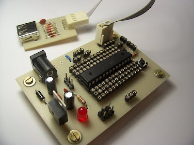
Serasidis says "Nowadays, USB is the most popular connection connection between PC and peripherals such as AVR programmers, printers, scanners etc. For that reason I had to modify my old serial AVR In-System-Programmer (ISP) to work with USB connection. You can say, "use a USB to Serial adaptor to connect your AVR ISP with your PC". Yes, that could be a solution but it would cost me more money than a singe FT232BM chip because I had to include an USB to RS232 adaptor and a power supply for my programmer. (almost €30)".

So, the solution was to replace the two transistors, that were used to adapt the RS-232 voltage levels to TTL voltage levels, with a USB to RS-232 chip such as FT-232BM.

This programmer worked perfect with AVRprog (zip file) but it could work with AvrOspII V5.47 also.

Download the source code, firmware, programming software, schematic and PCB for this programmer here
[source]

Wednesday, December 30, 2009

AVR Internet communications device

AVR Internet communications device
If you looking for Microcontroller project that controlled via internet protocol, well this project could be your reference to build it. Internet0 is a electronic project by Neil Gershenfield, Raffi Krikorian and Dany Cohen. The concept is a new network of physical objectsthat are IP enabled. Any items we use in everyday life would have the ability to communicate in IP, and thus send data over the internet in a standardized manner, without considerable electronics or cost.

This microcontroller project using AVR ATmega8 programmed ini C. For display they use LCD HD44780.

The main elements of the project are:

Transmission
to send a UDP internet0 protocol. Implementation:
o A circuit board with a Tiny15
o Assembly code to send the protocol
o Lines for power and signal
o An LED to troubleshooting and to indicate transmission

Reception
Translate the clicks to bits

PC Communication:
A program in Python that receives information from the serial port and transmit this into the internet

Read more

Tuesday, December 29, 2009

LM75 Temperature Sensor with 7 segment display output

LM75 Temperature Sensor with 7 segment display output
This is a test project built hastily on a solderless breadboard. It uses a LM75 to read the current temperature via I2C and displays the result on three 7 segment displays. It uses a PIC16F628 with an internal 4 Mhz clock. The program was created using JAL

[link source]

Sunday, December 27, 2009

MJoy- USB video game controller

MJoy- USB video game controller
This microcontrller project build using micrcontroller AT mega 8 and Xtal 12 MHz as the clock source.
"If you like to play video games in your computer as much as I do, you probably already heard about the MJoy, which is an USB joystick made by Mindaugas that uses an ATmega8 and have 24 buttons, one hatswitch (or POV or D-Pad depending on the game) and 6 analog axes." said Raijuu.

More information about this microcontroller project check the source here.

Saturday, December 26, 2009

Measuring Heart Rate on LCD using PIC

Measuring Heart Rate on LCD using PIC Did you know that The human heart can be measured optically. The heart beat with the varying blood pressure leads to a measurable change in the visual content of peripheral blood vessels. This is as good at the finger detect. There are two project work available, which were so far advanced that the optical signal pulse seized on a liquid crystal display graphically. Both works have been with a microcontroller PIC16C74 to collect and visualization of the signals.

Pulse measurement in a light
The light source was a red LED superhelle. The finger penetrating light was a light-frequency converter TSL230 detected. The period of the signal from the TSL230 was using the capture of the micro-controller unit with an accuracy of about 15-bit recorded. Through digital filtering 50Hz interfering signals were suppressed and the pulse signal extracted.

Pulse measurement in reflection
For the lighting of the skin's surface, an infrared LED used. the censor use PIN photodiode. With an analog circuit filters were equal light and high frequency interference signals eliminated. The signal was pulse by the A / D converter of the microcontroller with 8-bit digitized.

[Link]

Friday, December 25, 2009

LCD SWR Meter using PIC 16F88

LCD SWR Meter using PIC 16F88Measuring SWR at VHF/UHF frequency was never a fun. Most radio amateurs just assume that their 50 ohms cable is matching a beam or GP.

LCD SWR Meter presented here meet many simple task using a microcontroller PIC16F88. The very basic purpose to make this project is to encourage radio amateurs to build their own High Quality LCD SWR Meter at low price, instead of buying expensive ready made units.

[link]

Monday, December 14, 2009

Robot Project : Nickel-O-Matic

electronic robotic projectNickel-O-Matic was designed to entertain and provides gratuitous mechanical motion rather than efficient production. Nickel-O-Matic uses inkjet technology to print a custom message on both sides of 1-1/2" diameter blank wooden nickels. The robot uses a BASIC Stamp 2 to control much of the mechanical movement and a Propeller Chip to control the Inkjet system. The two controllers run a total of four hobby servos, three stepper motors, one DC motor, one DC vacuum pump, one inkjet head, and five IR sensors.


Mike Davey, the designer, said that the system was built as a number of modules to make design and trouble shooting simpler. The most complex of the modules is the inkjet system. At the center of the inkjet module is a spindle that rotates the wooden nickel under the inkjet head. This spindle is turned with a stepper motor and allows for repeatable placement of the nickel under the inkjet head. The spindle is also moved horizontally under the inkjet head by a second stepper motor coupled to a lead screw and slide mechanism. A Propeller Chip controls all the elements of the inkjet module. The Propeller Chip was chosen for the inkjet system for two reasons. The first is that the inkjet required fast and accurate timing. The Propeller Chip has direct control over the inkjet head through a simple Darlington transistor array. Each of the inkjet's 12 nozzles needs pulsed on for no more than 6 microseconds. The second reason the Propeller Chip was chosen is that the module needed at least 24 IO pins to control the inkjet module. The inkjet head needs 12 pins, the two steppers need 4 pins each, there are three IR sensors, and I needed at least one pin to communicate with the BASIC Stamp 2.

Download :


Source code

Sunday, December 13, 2009

PIC16F84 based Hexapod Robot

PIC16F84 based Hexapod RobotThis Hexapod Robot created by Mike Smyth. It uses 12 R/C servos for actuators. The 6 that raise and lower the legs are Hobbico CS-72 1/4 scale and the 6 that move the legs forward and backward are several brands of standard 1/10 scale servos (all are similar the Futaba S3003). The total robot weight is a little over 5lbs and the payload capacity is around 5lbs additional. The vertical travel of the legs is 1 7/8". Overall length and width is 13" X 11". When crouching, it's 5.5" tall. When standing up there is 3.5" of ground clearance under the body.


There are actually two PIC16F84's on the hexapod. The main processor contains all of the walking code and generates positioning pulses for all 12 servos. Twelve of the 13 I/O lines are used for switch inputs - one on the bottom of each foot and a contact sensor in the front of each leg. The servo pulses are output sequentially on the last I/O line. All the second processor does is de-multiplex the pulses from the main processor and send them to the appropriate servo

tag : Robotic, PIC16F84 Project, Electronic Design, Microcontroller Project (src)

Saturday, December 12, 2009

Minimechadon : PIC16F819 Based Walking Robotic

Electronic Project - PIC16F819 Based Walking RoboticMinimechadon is a great walking robot design by Mike Smyth. He creates Minimechadon to experiment with learning algorithms for walking. This walking robot weighs 12oz and has 4 degrees-of-freedom.

The sensor array consists of 4 touch sensors on the bottom of each foot, Left and right IR obstacle detection, and 4 CdS photo detectors located on all four sides of the robot. The heart of the control system is a Microchip PIC16F819 micro-controller and a separate 8 channel A-D converter.

The mechanical structure is built from brass tubing (which all the wiring runs through, UHMW (a high density plastic material), and PCBs. Perhaps the most striking aspect of the robot is the use of PCBs to create a 3D structure and mount all of the circuits/electronics.

tag : robotic design,PIC, Microcontroller, Electronic (src)

Friday, December 11, 2009

AVR Nikon Camera Remote Control

Nikon Camera Remote Control Microcontroller projectThis is an IR remote control for Nikon cameras. The circuit project is very simple: an ATtiny13V, button, transistor, resistor, IR diode and 3V battery. You can also connect the IR diode directly to the ATtiny13V, but that will limit the LED current and therefore the range. The project is compatible with the Nikon ML-L3 remote control. Supported cameras include: D40, D40X, D50, D60, D70, D70s, D80, and Coolpix 8400 8800. This project created by Dick Streefland

Thursday, December 10, 2009

Microcontroller Based Remote Sensing System

Microcontroller Based Remote Sensing SystemPageAlert is a flexible remote sensing platform connected to a data recording and alarm system. It is based on an MC13192 SARD board. This electronic project well designed by William Wittig. An MPXM2010 pressure sensor effectively senses the water level in a sump pump hole. The limited transmission range of ZigBee technology makes this wireless system ideal for home use.

Download
Project and Abstract

Wednesday, December 9, 2009

R/C Transmitter Range Tester

electronic circuit project - R/C Transmitter Range TesterThis project suitable for people who like with the transmitter system. It's an electronic analog project. You don't have to programming the IC to build it. The function of this electronic project is to measure the RF power being radiated from a transmitting antenna.

Among the Amateur Radio fraternity, a device such as the one described here would otherwise be known as a Field Strength Meter (FSM). Its main purpose would be to check that RF power is being radiated from a transmitting antenna. Some FSMs are tuneable across a wide range of frequencies, which allows the device to work with different transmitters and antennae - usually from HF to VHF and beyond. A difference with this unit is that it is only sensitive to those signals in the R/C section of the radio spectrum. The on-board trimmer allows you to tweak for maximum signal strength of your frequency of choice, whether it be 27MHz AM, or 40MHz FM.

In order to read the received signal strength, such a unit would ordinarily employ a mechanical analogue meter. The unit described here differs in that it uses four super-bright LEDs. The benefit of this is that it allows you to read the display from a distance - even in bright sunlight.

Download schematic(gif), PCB1, PCB2

Tuesday, December 8, 2009

PIC Project : Infra/radio remote control transmitter/receiver

PIC Project : Infra/radio remote control transmitter/receiverThis is a general purpose remote control project with programmable PIC microcontrollers. Schematics are shown for using infrared (RF) or radio (RF) media. If you are not familiar with microcontroller programming, you can use fixed encoder and decoder integrated circuits instead. Well-known such IC-s are Holtek HT-12D, HT-12E and Motorola MC145026, MC145027, MC145028.

Remote controls usually consist of encoder/decoder parts connected to a transmitter/receiver module which takes care of the transmission of digital signals by radio or infra waves. The format of this project's signal is designed to be ideal even for the cheapest ASK RF modules (using 50% signal/silence ratio), and it is similar to the Philips RC-5 format used in infrared remote controls. The transmitter has a varying number of buttons and sends the states of these inputs to the receiver. The receiver device decodes the message and sets the outputs accordingly.

Download schematic IR(jpeg), schematic RF
source

Monday, December 7, 2009

dsPIC MiniTron Amplifier

dsPIC MiniTron Tube AmplifierThe MiniTron is a high end vacuum tube stereo amplifier with efficiency, distortion, and power output enhancements provided by some unique circuitry featuring a dsPIC30F2023 controller IC. The dsPIC is used in this project to create a tracking buck converter whose output voltage tracks the audio signal. The unique SMPS resources in these IC’s do most of the "hard stuff" usually required in an SMPS design, leaving ample processing power available for other activities.

These IC’s and the Avago galvanic isolators are truly the "enabling technology" for this project. The controller IC is also used to perform system health checks, and set the operating points of the individual vacuum tubes. This allows total system programmability, offering several possible preset operating modes.

Download
Project Documentation

Sunday, December 6, 2009

dsPIC 33F128MC706 NUE-PSK Digital Modem

dsPIC NUE-PSK Digital Modem

PSK31 is one of the latest communications modes to capture the interest of hams worldwide. Its inherent ability to dig out low, near-inaudible signals is ideally suited for low power QRP enthusiasts. The PSK31 digital modem engine, however, requires intense DSP processing that is only commonly available in PC sound card. Thus the PSK operator desiring portability for field operation is locked into using a laptop computer as a controller, which results in a cumbersome station.

This project shows you design and construction of a standalone, battery-operated digital modem using a Microchip dsPIC microcontroller. The project includes a character display for transmit and receive text data, and a graphic display showing band spectrum and tuning indicator. Using GPL open source software, the modem can be homebrewed for less than $50 parts cost. When coupled with an SSB-capable transceiver or with a popular PSK-xx transceiver board from Small Wonder Labs, you too can have an effective portable PSK31 station.

Download
Project documentation

Saturday, December 5, 2009

AVR Digital Clock with Roman Numerals


This digital clock project will display a Roman number instead Hindu-Arabic numeral system (1,2,3... ). The project uses micro ATTINY2313 as main processor and LCD to display the clock. When you turn on the device, it will shows a screen flashes "Tempera tempus" as reminder to adjust the time.

The adjustment is done via the small button.
  • Press and hold the button for about 3 seconds -> hours appear on the screen -> release the button.
  • Press the button again and hold -> the hours advance from "I" to "XXIV" -> release the button on the time right.
  • Wait about 3 seconds -> minutes to appear on the screen.
  • Press the button and hold -> the minutes advance from "nothing" to "LIX" -> release on just minutes.
Unfortunately, you have to readjust the time after your turn off the power, because there is no RTC in this project.

Download schematic and source code here

Friday, December 4, 2009

Simple PIC RF/Microwave Frequency Counter

PIC RF/Microwave Frequency Counter

This RF/Microwave Frequency Counter project built based on PIC 16F876A. The basic counter rate is extended to at least 180MHz using two 74Fxx devices. A divide-by-64 prescaler is used for higher frequencies up to at least 4.5GHz. All results of the measurement are shown on an inexpensive, 2x16 alphanumeric LCD module with large characters.

There are 3 inpust on this project a microwave (prescaled) input, an RF input and a TTL input. The microwave and RF inputs are AC coupled and terminated to a low impedance (around 50ohms). The TTL input is DC coupled and has a high input impedance. A progress-bar indicator is provided on the LCD for the gate timing.

Both the microwave and RF inputs have an additional feature : a simple signal-level detector driving yet another bar indicator on the LCD module. This is very useful to check for the correct input-signal level as well as an indicator for circuit tuning or absorption-wave-meter dip display (Lecher wires). This project designed by Matjaz Vidmar.

tag : RF counter, Microwave Frequency counter, PIC project source

Thursday, December 3, 2009

AVR Shark Tag Project

microcontroller project animal tag

The goal of this project was to develop a shark tag working bench-top microcontroller platform. It is to be used for on-animal, in-situ data logging applications involving sharks and potentially other large pelagic.

The project used the Atmel Mega32 microcontroller to develop the core platform and functionality of a data archival tag. The project use temperature and pressure as sensor variable. The tasks ranged from logging sensor data to developing a simple user interface that requires only the addition of a laptop and a custom RS232 serial cable in the field.

It used an off-the-shelf SD (Secure Digital) card using flash memory for large capacity multi-read/write data storage. The microcontroller’s ADCs (analog to digital converters) were used to convert analog voltages produced by select sensors into digital format.

Tag: Animal Tag, shark, data logging, avr project src

Wednesday, December 2, 2009

XBOX Controller Controller

XBOX Controller Controller

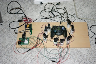
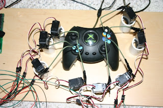
What is this? It's a system that will allow basically anything that can talk udp to control an Xbox. Why would you want to do this? I have no idea. I have my reasons, maybe you have some too. How this works: The XBOX buttons are physically pressed by arms (stiff wire) attached to servos that are controlled by a Basic Stamp 2. The BS2 is controlled by a gumstix over a serial port. The gumstix talks udp and accepts commands. So if you want to control an xbox, you basically have to talk a simple udp protocol to the gumstix.

xbc-c-controller

For this I tried 2 controllers, a PSP and a Nintendo DS. The udp protocol is simple. Build a message with the status of your controller, and the system takes care of moving the physical fingers on the xbox controller. The protocol is as follows: '!!' for start of message, and '##' for end of message. The juice of the message is a 1 character button identifier, followed by a 1 byte state. 1 means the button is pressed and 0 means button is not pressed. Here is a sample message:

!!U0D0L0R1A1B0X0Y0##

The message should be self explanatory. So the controller (in this case the psp or nds) polls inputs every so often and then dumps the state. I had it all working at every 100ms, but then something happened - not sure what - so I backed it down to every 250ms. The bottle neck is on the BS2, and to keep things consistant, I just kept all polling intervals the same.

The app on the gumstix consists of 2 threads. One listens for udp commands and the other babbles out the serial port at 38.4k. The serial thread wakes up every 250 ms and sends the status of all buttons to the BS2. The status is stored in global variables that are updated by the udp thread whenever the controller sends an update.

The serial protocol to the BS2 is simple. A 'A' signifies a start of message followed by 8 bytes of status for each of the buttons currently supported. The PIC decodes this message and tells the servos to respond accordingly.
xbc-c-pic

PIC Cactus LED Display

LED Cactus Display PIC Project

LEDactus is LED display project that resemble Cactus. It used PIC microcontroller 18F1320 as controller of the LED. LEDactus is immobile and attempts to survive by creating a pleasant display. It can produce more complex and mesmerizing displays. And in the latest generations, a sense of touch is added to allow the LEDactus to interact with passersby.

term : LED display, electronic cactus, PIC project (src)

Tuesday, December 1, 2009

USB PIC Programmer

If you start learning PIC microcontroller, you need PIC progrmmer to "fill" your PIC with compiled source code. You can build your own PIC programmer like USBPICprog project.

Usbpicprog is an USB in circuit programmer for Microchip PIC processors. The hardware is as simple. The latest version only contains one PIC18F2550, 3 mosfets, and besides the connectors a hand full of passive components.

download
Open source programmer